PCBs
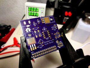
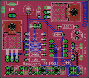
I’ve recently received the first and second revisions of my Raspberry Pi – PSU Through-Hole PCB. They came out pretty well if I do say so myself.
There are a couple of issues with the R1 and R2 designs that have already been addressed in R3, but since the R3 is not here yet, let’s populate an R2 board and test it out.
We will need to start with the power rail. It’s pretty straight forward – Just like my original prototype, the board takes in 5V which is used to power the Raspberry Pi directly. The micro-controller is powered by a 3v3 rail (hence the LD33V), this reduces power consumption but more importantly makes the micro compatible with the Raspberry Pi’s GPIO.
Programming
After I filled in the power stage, I proceeded to flash the micro using my MKII and some pogo pins.
I tested the board and since it all checked out fine, I proceeded to populate the rest of the components.
Moment of Truth
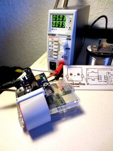
I pulled out one of my RPis and hooked up the fully populated PSU.
No blue smoke came out, which is always good, hooray! :)
Revision 3
The third revision of the PSU PCB has already been sent to the fab and is under production at the moment of writing, I’ll record a video as soon as I get it showing how it works and how you can build your own!
Update
I got my Rev3 board in, check it out by clicking the link below:
Make your own Raspberry Pi – PSU [R3]
OSHW
The source code, schematic and board layout for this project is publicly available on GitHub.
GitHub Repository


